Correct connection Arduino Nano ver.3 9-10 FreeIMU GY-80 GY_80
Step by step (NO RESISTOR)
Multiwii MWC, NanoWii ,Chinese 10DOF (code name GY-80, GY_80) and Arduino Nano ver.3 connection
and testing
Hi. My name is Brig. I see more inf for NanoWii and FreeIMU.
Here it is Arduino 328 chip what the Multiwii software configuration file config.h identify
GY_80 or GY-80.
ADXL345 : 3 axis accelerometer
L3G4200D : 3 axis gyro
BMP085 : atmospheric pressure sensor
HMC5883L 3 axis digital compass
Next steps - download programs.
The code runs on Arduino
http://arduino.cc/en/Main/Software and it is compatible with a large variety of sensors (the GY80 being one of them).
MultiWii
http://code.google.com/p/multiwii/downloads/list Open in Arduino folder MultiWii
At the top of the table to open the file - Config.h
Uncomment you Quad
Uncomment the following line in the GY-80 or GY_80 your IMU
How to use the I2C bus with the IMU, which has at least 4 different I2C addresses for management for Quad?
Everybody writes that resistance in the circuit needed to connect.
I can not believe, so let's look ORIGINAL DATASHEET !!!
And sensors are generally..not only GY 80.After checking, I found this. See the red arrows opposite voltage for each sensor.
From this it is clear that we need to connect up to 3 volts
And if you connect the 5 volts - we increase the voltage by 60-70%, are not designed in the datasheet. This is dangerous!
You Need resistor for
undervoltage
Port Scanning I2C bus gives this result
 Connection GY-80
-VCC_IN
-VCC_3V
-GND
-SCL
-SDA
-M_DRDY
-A_INT1
-T_INT1
-P_XCLR
-P_EOC
Pins are IF CONNECT 5 VOLT !!!!!!!!!!: Arduino A4 -> GY-80 SDA
Arduino A5 -> GY-80 SCL
Arduino 5V -> GY-80 VCC
Arduino GND -> GY-80 GND
When you connect - sensors work like mad, even when they do not touch - no movement at all.
My filed them more stress voltage than you need. See gif.
But there is a pin board Nano 3.3 volts DATASHEET.
Now, connect to it and see.
Arduino A4 -> GY-80 SDA
Arduino A5 -> GY-80 SCL
Arduino 3.3V -> GY-80 VCC Arduino GND -> GY-80 GND
As you can see - all the sensors are working in the correct position and calmed down. And as you can see - there is no need IN NO resistor
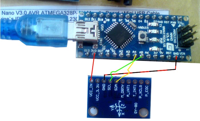
Connection - gif. See number by color
1 to
1
2 to
2
3 to
3
4 to
4  AFTER
AFTER: All sensors only work when driving, look straight line when the sensors in the quiescent condition with no movement
 I2C speed
The sensors react only to movement and calm and confident.
100kHz normal mode
400kHz fast mode, it works only with some WMP clones
The frequency of the sensors can be 100 or 400 kHz, it is necessary to uncomment .... but this also depends on battery consumption during the flight
Successful flight of Brig - site
http://quadro.ucoz.ru/ Good luck